Making your own home automation sensor is not that difficult or expensive. You need a sensor and a microcontroller board that wirelessly transmits the sensor data to your home automation controller. In this article we connect temperature, humidity and air pressure sensors and an LCD screen to an ESP8266 WiFi Module. We install the ESP Easy firmware on it and integrate our sensor with the open source Domoticz home automation system, so that you can read the measurement data in the dashboard of your home automation controller. Your own home automation system in 17 steps!
01 ESP8266
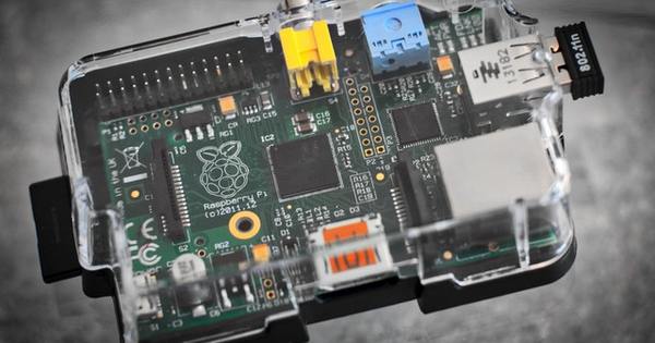
The heart of a home automation sensor consists of a controller board that reads in sensor data and forwards it to your home automation controller. A popular choice among DIYers are boards based on the ESP8266 WiFi Module, produced by the Chinese company Espressif Systems. The controller operates on a clock frequency of 80 or 160 MHz, has 64 kilobytes of instruction memory and 96 kilobytes of data memory, 512 kilobytes to 4 megabytes of ram, 802.11 b/g/n Wi-Fi and 16 gpio pins for communication with the outside world. The AI-Thinker controller boards are especially popular, especially the minimalist ESP-01 with 6 usable pins and the ESP-12E with 20 usable pins.
02 ESP Easy
The hardware alone will get you nowhere: the firmware that runs on the ESP module determines the function of the controller board. Originally, the NodeMCU firmware was a popular choice for the ESP8266, but the Arduino firmware is now also supported. The interesting thing about the latter is that you can then develop programs for the ESP module with the Arduino IDE. And the developers of the ESP Easy firmware make it even easier for us: ESP Easy turns your ESP module into a multi-sensor device that you can easily configure via a web interface.

03 Firmware Download
At the time of writing, the developers of ESP Easy are overhauling their firmware. We therefore do not opt for the stable release, but for a development version of the completely rewritten version 2.0. Download the zip file (in our case it was ESPEasy_v2.0.0-dev11.zip, which turned out to be very stable in practice) and extract it. In addition to the source code, you will also see all kinds of bin files. That is the binary version of the firmware. The names make it clear which one you need: normal contains only the stable plugins, test also the test plugins and dev also the plugins that are still under development. 1024 is for ESP modules with 1 MB flash and 4096 for ESP modules such as the ESP-12E with 4 MB flash.
04 Flash Firmware
We illustrate this article with the ESP-12E, which has a micro USB connector with a built-in USB-to-serial converter for serial communication with your PC. First, download the CP2102 drivers from the Silicon Labs website. Then connect the ESP module to your PC via USB. If you use a different model of ESP module, you still need a USB-to-TTL converter, which you connect to the gpio pins of your module. See the ESP Easy wiki for more information. Flashing the firmware is done with the tool FlashESP8266.exe in the zip file containing the firmware. Choose the serial port (eg COM0) and the bin file with the desired firmware.

05 Wifi configuration
When the freshly flashed ESP module boots up (press the RST button on the board after flashing is complete), it functions as a wireless access point with ssid ESP_Easy_0. Connect to it via your smartphone or other WiFi device and enter as password configesp in. After that, open your web browser, which will redirect you to the captive portal of the ESP module. Choose which ssid you want the ESP module to connect to and enter the corresponding password. Press Connect to set up the connection.
06 Password
If the ESP module has managed to connect to your WiFi, you will be shown the IP address. Now reconnect your smartphone to your normal WiFi and then visit your web browser (which is now possible on your PC, a larger screen is more convenient now) the IP address of the ESP module for the rest of the configuration. In the tab Config It is especially important here that you give your module a unique name and choose an administrator password, so that not everyone on your local network is able to change the configuration. Press at the bottom Submit.
07 Add Domoticz controller
In the tab controllers A controller is already added by default with the Domoticz protocol. Click next to it edit. As protocol you let Domoticz HTTP to stand. Enter the IP address and port (8080 by default) of your Domoticz controller. If you have protected the Domoticz web interface with a username and password, enter that here as well. Finally tick Enabled on and click Submit. If you press Close afterwards, you will see your Domoticz controller in the list of controllers.

08 Status LED
In the tab Hardware define what you use the gpio pins for. A useful feature that is new in version 2.0 of the firmware can be found under Wi-Fi Status LED. If you enter there the pin number to which an LED is connected, ESP Easy displays the status of WiFi on that LED. And that is also possible with the built-in LED of the ESP module. Choose that GPIO-2 (D4) and tick Inverted LED on because that led is active-low. Click at the bottom Submit. If ESP Easy is not connected to Wi-Fi, the LED will now flash quickly between bright and soft.
09 Sensors and display
Now take a breadboard and place the ESP module (not connected to the power supply!) and a BMP180 sensor board on it. The latter is a printed circuit board with a temperature and air pressure sensor. Now connect VIN on the BMP180 to 3V3 on the ESP module, GND to GND, SCL to D1, and SDA to D2. Now take the AM2302 (DHT22) temperature and humidity sensor, connect the red wire to VIN, the black wire to GND and the yellow wire to D5. Finally, connect the OLED screen with SDD1306 controller: VCC to VIN, GND to GND, SCL to D1 and SDA to D2. Then reconnect the ESP module power supply.
10 Virtual sensors in Domoticz
Create a dummy sensor in the Domoticz web interface. To do this, open the menu Settings / Hardware, choose new hardware from the list of type dummy, give the device a name and make sure Active is checked. click on Add. Then click on the virtual device Create virtual sensors. Give the sensor a name and choose the type Temp+Hum. click on OK to create the sensor. Then locate the sensor in Settings / Devices and write the number in the column idx. This is the ID of the sensor. Then add a sensor of type in the same way Temp+Baro.

11 Configure DHT sensor
Now open the ESP Easy web interface. Click in the tab Devices in the first row on edit. Choose at Devices in front of Environment - DHT11/12/22. Give the sensor a name and check Enabled at. Choose as GPIO pin GPIO-14 (D5) and as sensor type DHT 22. Enter the ID of the sensor in Domoticz at IDX and make sure that Send to Controller is checked. Then click Submit. Then click on close, you will see the sensor in the list of devices, including the current temperature and humidity. You will also see the data in Domoticz.
12 Configure BMP sensor
The BMP180 sensor communicates with the ESP module through the I2C interface. So first look in the tab Hardware from ESP Easy to verify that the I2C interface is configured correctly: GPIO-4 (D2) at SDA and GPIO-5 (D1) at SCL. These are also the connections you made on the breadboard. Then go to the tab Devices and click in the second row on edit. Choose as device Environment - BMP085/180. Give the sensor a name, check Enabled and enter the altitude of your location in meters (to compensate for air pressure). Enter the correct ID of the virtual sensor in Domoticz and click Submit.
13 Create your own rules
During the editorial closing, there was another error in ESP Easy that caused the firmware to not correctly send the air pressure from the BMP sensor to Domoticz. Fortunately, ESP Easy is flexible enough to solve this. To do this, first check your BMP sensor Send to Controller off and click Submit. Then open the tab Tools, click on Advanced, Finch Rules on and click Submit. A new tab will now appear Rules. open this. You can now easily add your own rules in the text field.

14 Timer
In the text field, add the script below. Replace the IP address, port number and ID with the values for your situation. This script sends the sensor data to Domoticz every minute. Reboot the ESP module afterwards Tools / Reboot.
On System#Boot do
timerSet,1,60
endon
On Rules#Timer=1 do
SendToHTTP,192.168.1.101,8080,/json.htm?type=command¶m=udevice&idx=230&nvalue=0&svalue=[BMP#Temperature];[BMP#Pressure];BAR_FOR;ALTITUDE
timerSet,1,60
endon
15 Configure OLED screen
Then we only have to configure the OLED screen so that we can also see the sensor data on it. First click in the tab Tools on I2C Scan and see what I2C address the oled screen uses, 0x3c by default. Then create a third device in the tab Devices and choose as type Display - OLED SSD1306. Choose a name, tick Enabled and check whether the correct I2C address is entered. Also choose the correct rotation (normal or upside down) and screen size.

16 Show sensor data
In the rest of the configuration of the OLED screen, you choose what appears on the screen. You have 8 lines of 16 characters to fill. Fill on line 1 T: [BMP#Temperature]^C in, on line 2 H: [AM2302#Humidity]% and on line 3 P: [BMP#Pressure] hPa. We use the temperature of the BMP180 because it is more accurate than the DHT22. click on Submit. After a minute (the default delay) you will see the sensor data on the screen.
17 Other sensors and actuators
The sensors and the screen that we connected in this workshop are of course not the only supported devices. Here you will find a list of all plugins. Here you can also see which plug-ins are included in the normal firmware and for which you need the testing or development firmware. A plugin's wiki page tells you how to connect the device and how to configure the plugin in ESP Easy.

Battery powered IoT sensor
ESP Easy is useful for turning an ESP module into an IoT device. But you don't want to hang that on the wall all the time with a USB power adapter. Fortunately, the ESP module can also be powered by batteries. You do have to perform a number of tricks to limit the power consumption. Read this page on the ESP Easy wiki. Broadly speaking, the bottom line is that your ESP module should be in sleep mode for as long as possible. For example, you only measure the sensor value once an hour and only then switch on WiFi. Also choose the correct ESP module. For example, the Wemos D1 mini is an economical model that continues to work for a year on three AA batteries with some effort.